Blog · · Andrii Shylenko
Bolted joints from one fastener table
The model above is a flange with eight M6 bolts. Drag it to turn it. Every screw, washer and nut in this post comes from one table of ISO metric fasteners, and the table picks the sizes each joint needs.
One table, not a pile of models
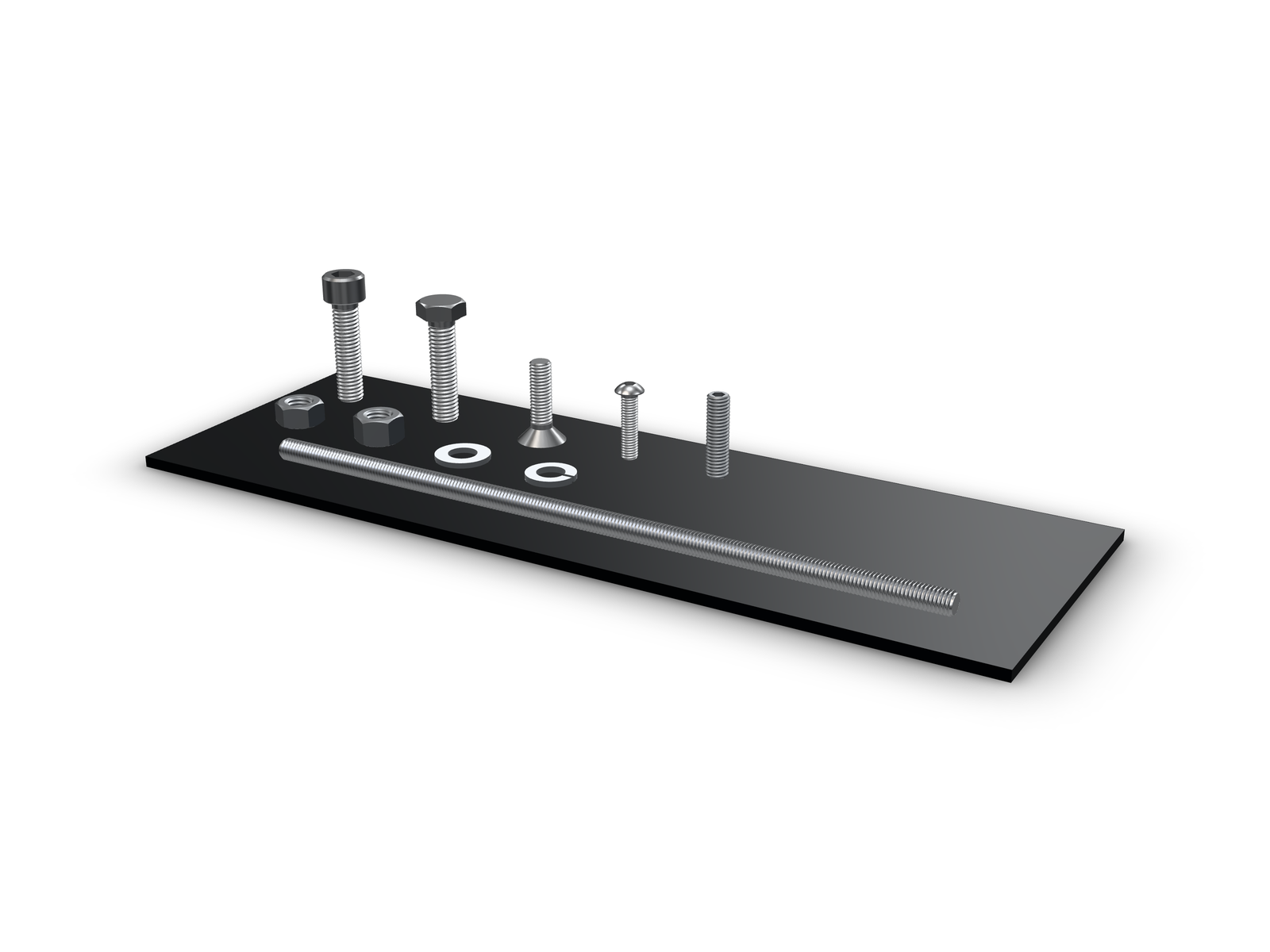
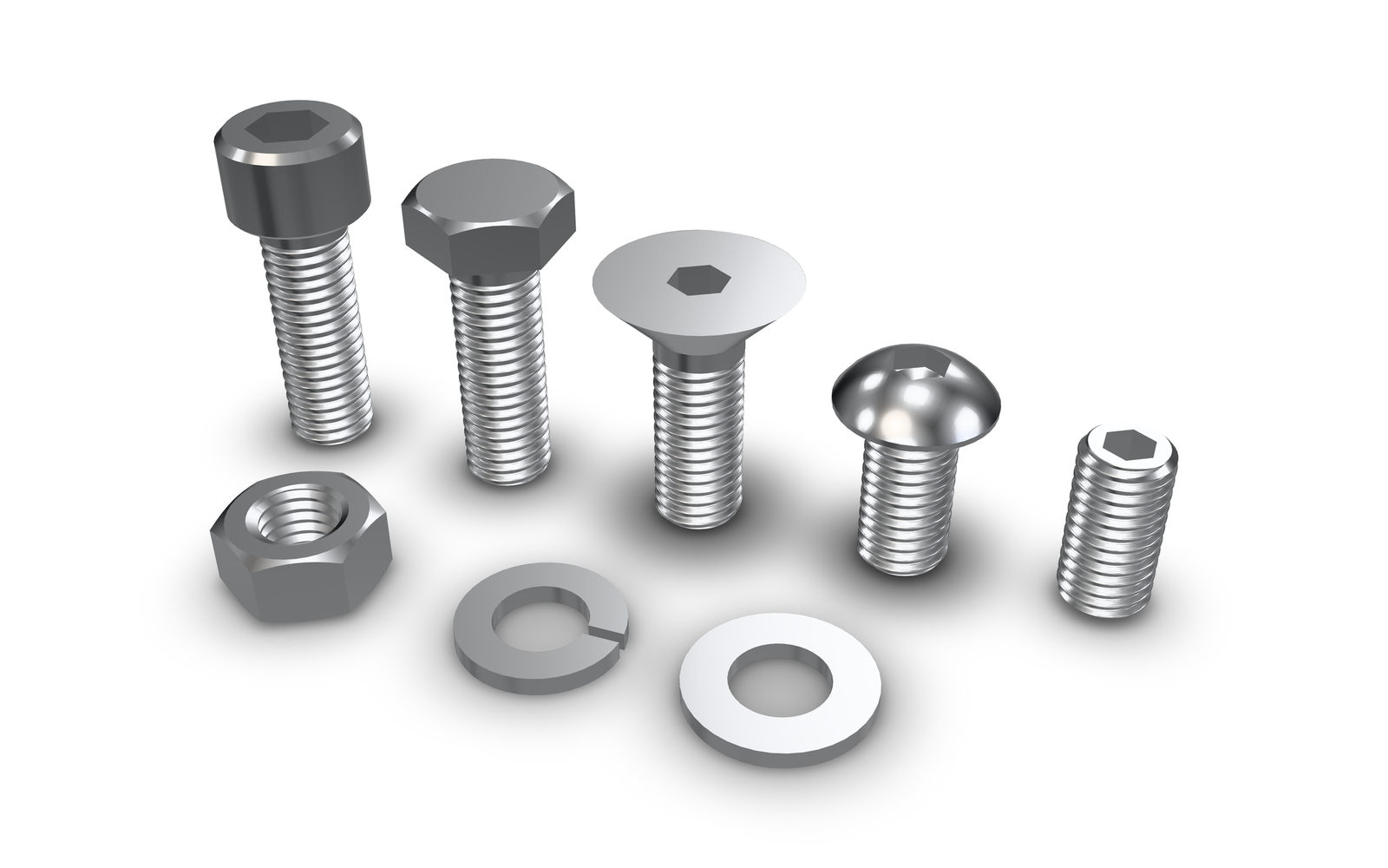
kernelCAD knows socket-head, button-head, countersunk and hex-head screws, set screws, threaded rod, hex nuts, lock nuts and washers. Sizes run from M2 to M20 where the standard has a size, and the lengths are the lengths suppliers stock. If you ask for an M2 × 50 that does not exist, it says so and lists the sizes that do.
A lap joint
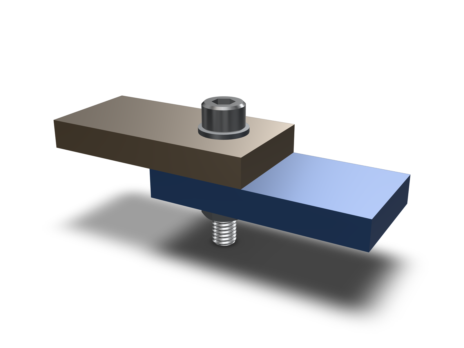
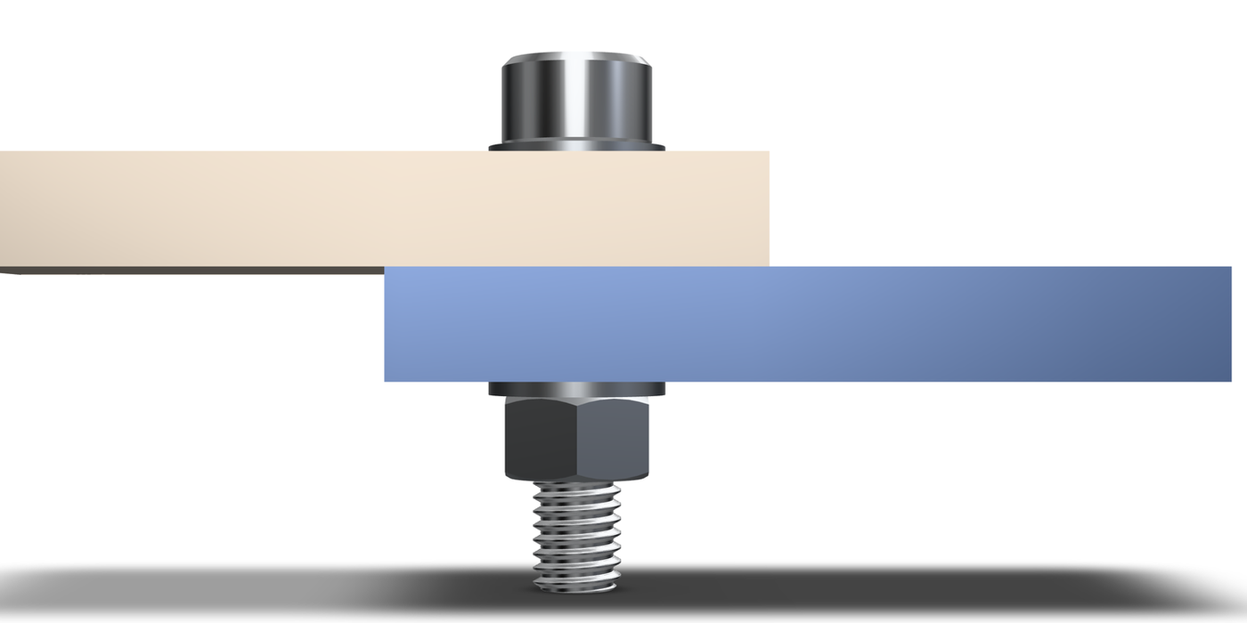
Two 6 mm bars overlap by 24 mm. One M5 bolt holds them. You give the grip (12 mm) and the mode (bolt), and the table returns the screw length plus the members.
The stack is 12 mm of bars, a 1 mm washer, a 4.7 mm nut and two thread pitches past the nut: 20.3 mm. The next stocked length is M5 × 25, which leaves 6.3 mm of thread showing. If no stocked length can reach the grip, the call fails and tells you the length it needed.
Holes you already drew
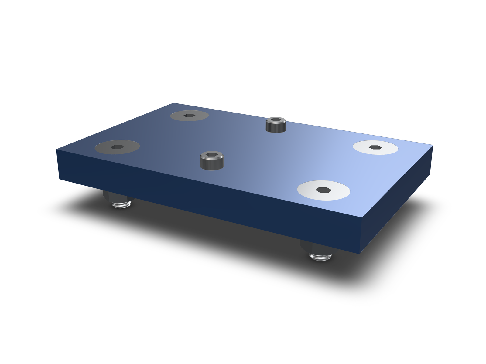
The other direction starts from the part. The plate has four Ø5.5 holes and two Ø3.4 holes. Ø5.5 is the normal clearance for M5, so the four holes take M5 screws. Ø3.4 is the normal clearance for M3, so the two holes take M3 screws. kernelCAD covers every hole with the same diameter and axis, so a pattern costs no extra work.
For a flat-head screw it cuts the 90° countersink the head needs. For a socket-head screw it leaves the hole as drawn. The washers and nuts land on the back.
A flange ring
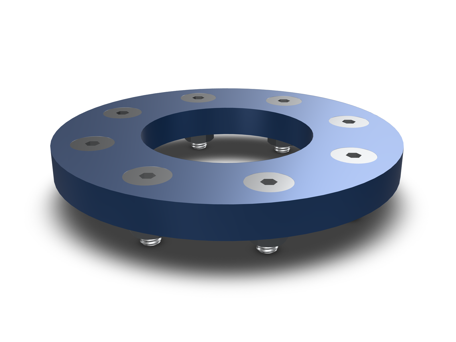
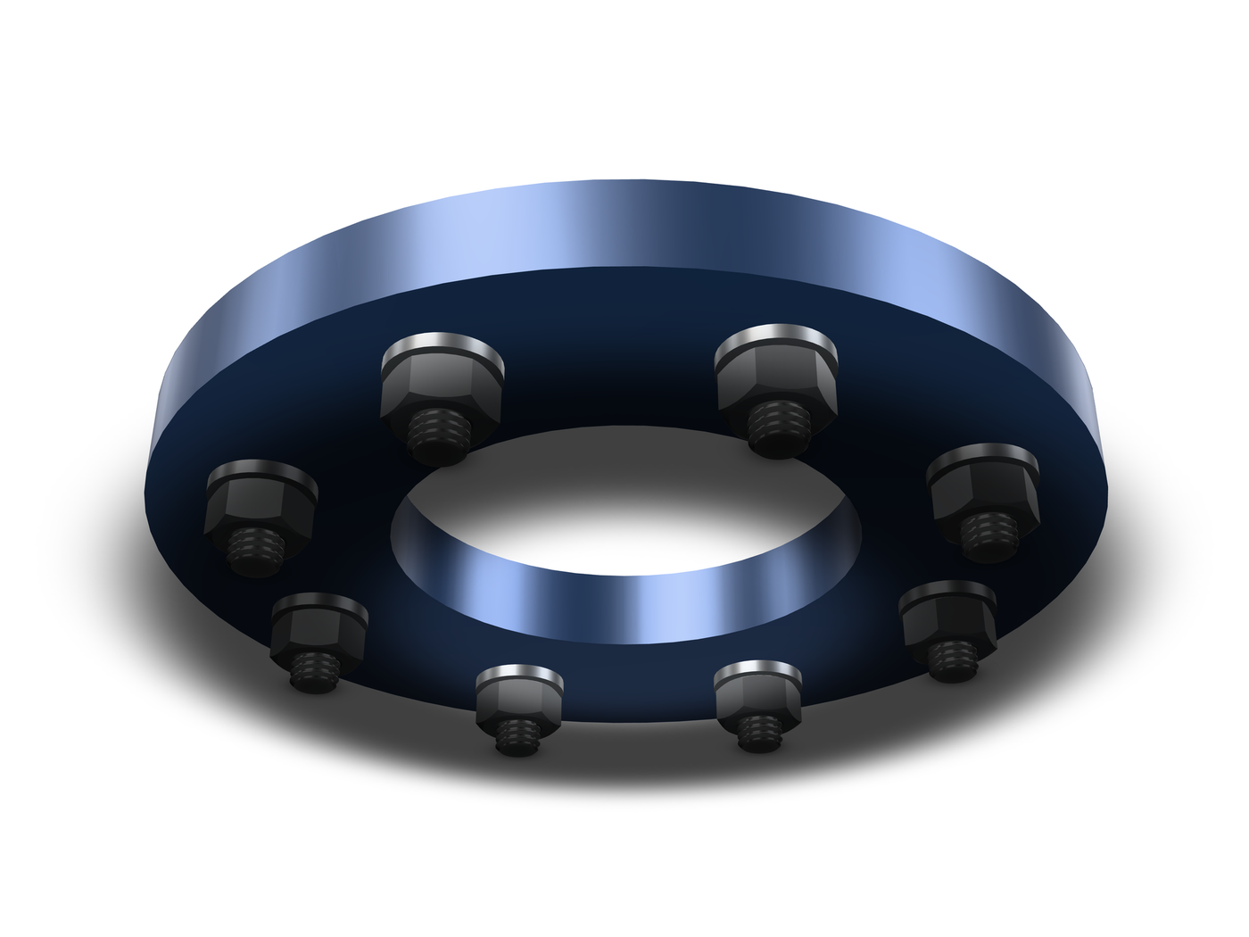
The ring has eight Ø6.6 holes on an 85 mm bolt circle and is 10 mm thick. Ø6.6 is the normal clearance for M6. With a 1.6 mm washer and a 5.2 mm nut, the stack needs 18.8 mm, so each hole gets an M6 × 20 bolt. One call covers all eight.
Fits
ISO 273 gives three clearance classes. For M6 they are 6.4 mm close, 6.6 mm normal and 7.0 mm loose. The table matches the hole to the thread and reports the class, so a plate drilled for a loose fit still gets the right screw. The match tolerance is 0.1 mm, which keeps a 5 mm tap drill from reading as an oversized M4 hole.
Limits
All sizes are nominal table values. The threads are drawn at the ISO coarse pitch, but they are not certified hardware. The spring washer is drawn flat with its split, without the twist. Checks use the nominal size, so a modeled thread inside its nut is not reported as a clash. Mass and volume come from the drawn solid.
The model above is the flange example. Drag it. The same table runs in Studio and through the MCP tools.